Safeties and Protections
What the firmware does when voltage, current, temperature, or engine speed leaves the safe range. Each protection below lists its trigger, the action taken, and the variable names to grep for; user-adjustable thresholds persist in non-volatile storage (NVS, via settingWrite() / settingRead()), while a few are deliberately hardcoded or derived.
The protections share a small set of mechanisms — a set of field-drive ramps, an immediate cut, and a cooldown lockout — defined once below, then referenced by name. Everything is decided in 6_functions.ino.
How a protection reaches the field
Every control tick, two pure functions look at a snapshot of the world (TickSnapshot, built by buildTickSnapshot()) and decide what should happen. They must always agree, so they are written to mirror each other:
selectFieldControlMode()returns the control mode — which ramp or normal-loop behavior to run.selectFieldEventReason()returns the reason — the named cause, used for telemetry (the field-off banner) and to decide whether the reason warrants an instant cut.
A third function, shouldImmediatelyCutGPIO4(), marks the reasons that chop the field the same tick instead of ramping it down. When a reason is on that list, the field-enable line (GPIO4) goes low immediately via applyImmediateCut(); otherwise the mode's ramp runs in runShutdownPath().
The reason check runs twice: once before the current-sensor freshness gate (the "pre-gate" pass, so a dead current sensor can't freeze the field high), and once on the main path. Both call the same selectFieldEventReason(), so they short-circuit identically.
The priority ladder
Both decision functions walk the same ordered list and return on the first match. Order is the safety model — anything above a given rung wins over everything below it:
- INA228 hardware over-voltage latch — the battery monitor's own alert fired.
- Hard overcurrent — measured alternator current over the electronic-fuse trip.
- Charging disabled — the user On/Off switch (or an external disable) is off.
- Fast over-voltage — live voltage over the absolute ceiling. This rung sits above manual mode and is not gated by the test switch.
- Manual mode — the user has taken manual control. Everything below this rung is bypassed in manual.
- RPM gate — engine speed below the field minimum.
- Tach-lie plausibility — the tach claims the engine is running while a hard-driven field produces no output.
- Cold-charge lockout — battery too cold to charge.
- Critical conditions — temperature-data stale, current-data stale, voltage implausible, voltage-sensor disagreement (critical), critical over-temperature.
- Warning conditions — voltage-sensor disagreement (warning), over-temperature (warning / sustained).
- Cooldown lockout — a prior fault's lockout is still counting down.
- Commissioning idle rest — the guided wizard is holding the field low between steps (not a fault).
- Normal automatic control.
The two ungated, above-manual rungs (1–4) are why the hardware alert, hard overcurrent, and the software absolute-OV trip fire even in manual and Limp Home; everything from the RPM gate down is automatic-mode only.
Notation and shared mechanisms
Two voltage sensors
BatteryV— measured by the ADS1115 analog converter.IBV— measured by the INA228 battery monitor. This is the signal for all software voltage protections;getBatteryVoltage()returns it.
BatteryV is the second opinion: it is used by the cross-sensor disagreement check and by the implausibility and near-zero/not-a-number checks below. The INA228 also has a hardware alert pin that operates on the chip's own internally averaged voltage, independent of firmware.
The field-drive paths
| Path | Behavior | Used for |
|---|---|---|
Immediate cut (applyImmediateCut()) |
Field-enable line low within one tick, PWM zeroed, control loop reset, system drops to fault state. Held while the condition persists, then resumes automatically when it clears. | Hardware-OV latch, software absolute-OV trip, hard overcurrent, RPM below minimum (the basic gate and the engine-stopped fast cut), tach-lie plausibility, current-data stale, critical temperature |
Warning ramp (MODE_WARNING_RAMP_AND_LOCKOUT) |
Staged ramp-down: slew duty to the tach-keepalive floor at the normal ramp rate, optional hold, then a slow ramp to zero, then a settle period before the enable line is cut. Arms the cooldown lockout. | Sensor-disagreement warning, temperature warning / sustained, cold-charge lockout |
Critical ramp (MODE_CRITICAL_RAMP) |
For a critical voltage-sensor fault (disagreement-critical or implausible) it jumps straight to the final settle-and-cut; every other critical reason (notably temperature-data stale) runs the full staged ramp. Arms the cooldown. | Temperature-data stale, voltage implausible, voltage disagreement critical |
Disabled / lockout ramp (MODE_DISABLED_RAMP, MODE_LOCKOUT_RAMP) |
Ramp to zero and hold. The disabled ramp is the user On/Off switch (no cooldown). The lockout ramp runs while an already-armed cooldown counts down. | User charging Off; cooldown countdown |
The ramp shape is user-tunable (DutyRampRate, default 40 %/s; DutySlowRampRate, 0.5 %/s; ShutdownPhase2HoldMs, 500 ms; SettleTimeBeforeCut, 1000 ms). See runShutdownPath(). The staged ramp runs phases 1 → 3 → 4 (there is no phase 2 — the "phase-2 hold" is a timer inside phase 1).
Mode and reason are decided separately, and where they disagree the reason wins: RPM-below-minimum, tach-lie and critical temperature all select the critical-ramp mode, but their reason is on the immediate-cut list, so the ramp never actually runs. The mode value still matters — on the following tick, with the enable line already low, it is what arms the cooldown lockout.
The cooldown lockout
After a warning- or critical-ramp shutdown, charging is locked out for a cooldown period held in activeCollapseDelay, which is chosen by reason:
- RPM below minimum →
RPM_RECOVERY_DELAY(500 ms), so charging resumes quickly on restart. - Software absolute over-voltage → the adaptive ladder (below).
- Everything else →
FIELD_COLLAPSE_DELAY(30 s).
When the delay elapses the system retries; if the fault persists a new lockout begins.
The adaptive over-voltage ladder (nextFastOvLockoutMs()) starts at 0.5 s and doubles every third fire — 0.5 s, 1 s, 2 s, 4 s, 8 s — capped at 10 s. A clean stretch of 60 s with no fire resets it to 0.5 s. It lives in volatile RAM, so a reboot restarts the ladder.
Arming scope of the throttling protections
The overvoltage current-trims (Groups 1–2), the current-excess supervisors (near-target and below-target), and load-dump detection arm only while the voltage-holding loop is engaged (voltageControlActive — absorption, float, and the voltage-holding override modes). Three extra conditions narrow this:
- Group 1 additionally waits until measured voltage is within a small guard band of the target (
PRED_GUARD, hardcoded at 0.06 V per 12 V of bank) so it cannot fire during normal ramp-up far below target. - The current-excess supervisors additionally disarm in zero-current float (
MaintainMode/zeroFloatActive), where the command carries no meaning to compare current against. - Zero-output stand-down (
altZeroOutput) disarms Groups 1–2 and the near-target current-excess supervisor whenever the alternator is delivering essentially nothing into a bus that is nonetheless above target. A protection whose actuator cannot move the protected variable must not fire: with the alternator at about zero amps, the excess is authored by the battery's own resting voltage or by another charge source (solar, shore, DC-DC), so cutting the field removes nothing — while each no-op fire still costs a tach false-zero, an integrator reseed, an OV-episode derate, and a lockout tier. The zero band scales with the configured current-sensor full scale, entry requires a 2.5 s dwell (so a normal decay through target cannot latch it), and the exits on current, voltage-control state, or stale data are single-tick, because an RPM rise at unchanged field regains real output with no warning. The voltage leg alone is hysteretic: entry is strict on raw voltage (above target), but from the first tick of the entry dwell onward the leg reads the Group-2 filtered voltage against a looser bar (target − about 50 mV per 12 V of bank). The wind-down glide parks the target roughly 20 mV under the bus, so a strict raw comparison chatters at ripple rate — the dwell never completed, and a completed latch would have chattered the same way. The absolute layers — the software hard cut, the INA228 alert, hard overcurrent and load dump — stay armed throughout. While it holds, the dashboard limiter code reads 7 ("battery above target").
A dashboard test switch (testProtectionsEnabled) can disarm the trim and current-excess layers for plant-characterization tests; load-dump detection and the hard cuts are not affected by it.
Separately, each group carries its own persistent Enable toggle on the Protections page — HardOCEnable (Group 0), OvGroup1Enable, OvGroup2Enable, IExcessEnable (Group 3, gating both current-excess supervisors), BattLimitEnable (Group 4), and LoadDumpEnable (Group 5). The tach-lie plausibility cut carries the same kind of switch, TachLieEnable (see Tach-lie plausibility cut). All of these are independent of the test switch, and for the three layers the test switch deliberately cannot reach — Group 0, Group 5 and tach-lie — the layer's own toggle is the only way to disarm it, so turning one off removes the last over-current, load-dump or phantom-RPM backstop respectively.
The layers are split by the signal they watch: Groups 1–2 watch battery voltage; both current-excess supervisors watch alternator current; load-dump watches battery current. There is no battery-current over-current supervisor — an earlier battery-current variant was removed, and battery current now survives only as the load-dump input and as the separate BattCurrentLimitA limit.
Overvoltage protections
Several distinct mechanisms, from gentle to absolute. The voltage and current trims are throttling protections: they keep charging but lower the current setpoint cap (fastOvCurrentCap) so voltage stops rising. Load dump and the hard cuts take the field down. The INA228 hardware alert is the final backup that works even if firmware hangs.
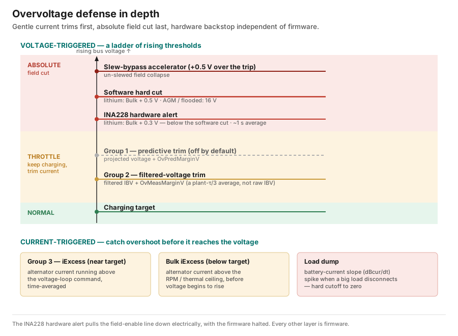
Whenever any trim engages, the duty slew limit is removed (GOV_BYPASS_SLEW) so the current loop can collapse the field at full speed, and the inner current-PID integrator is reset so duty falls within a cycle or two.
Group 1 — prediction-based trim
Projects where voltage will be a fraction of a second from now and trims the current cap if the projection overshoots. Off by default (OvGroup1Enable = false) — on a belt-driven alternator the derivative term amplifies belt ripple.
- Trigger: projected voltage (
IBVplus the lookahead horizonTdPredtimes the smoothed rate-of-rise) exceeds the active target byOvPredMarginV, onceIBVis withinPRED_GUARDof the target. - Action: lowers
fastOvCurrentCapproportionally to the projected excess (slopeKHard, amps per volt). - Knobs:
OvGroup1Enable,TdPred(0.045 s),OvPredMarginV(0.15 V per 12 V),DvdtTC(rate-of-rise smoothing time constant, 58 ms),KHard(35 A/V, shared with Group 2). No hold latch — it re-evaluates every tick.
Group 2 — filtered-voltage trim
The workhorse voltage layer (OvGroup2Enable = true). It fires on a filtered voltage, not the raw reading: ibvFilt is a smoothed IBV whose time constant is derived from the commissioned plant response (one-third of the plant time constant, clamped 10–80 ms). Raw IBV false-fires on belt ripple; the filter is never a user knob.
- Trigger:
ibvFiltabove the target byOvMeasMarginV(0.1 V per 12 V). - Action: lowers
fastOvCurrentCapproportionally to the filtered excess (slopeKHard), and increments the lifetime soft-cap counter. - Hold and release: once engaged it holds the clamp while
ibvFiltsits anywhere in the band between the target and the trigger point (hysteresis). It releases on the earliest of: the filtered voltage falling back to the target; the filtered rate-of-rise crossing its peak (dvdt <= 0); or the field-decay early release (see Recovery). - Knobs:
OvGroup2Enable,OvMeasMarginV,KHard.
Group 3 — current-excess supervisor near the target (iExcess)
Catches overshoot before it shows in voltage, by noticing that measured alternator current is running well above what the regulator is commanding. The detector works on the time-averaged excess, so it is invariant to disturbance frequency, amplitude, and alternator size.
- Signal: a dt-aware exponential average of
(MeasuredAmps − command), time constantIExcessTau(75 ms). Averaging first means any zero-mean fluctuation cancels before the threshold is checked, so a brief spike cannot trip it. Near the target the command is the voltage-loop setpoint (setpointLimited). - Trigger: the averaged excess crosses an affine threshold
E = clamp(IExcessFrac × command + IExcessBaseA, IExcessFloorA, IExcessCeilA)— a fraction of the command (IExcessFrac, 0.031) plus a fixed intercept (IExcessBaseA, 5.8 A), floored atIExcessFloorA(5 A) and ceilinged atIExcessCeilA(20 A). - Arm gate:
voltageControlActive && MaintainMode == 0 && !zeroFloatActive && IBV > target − IExcessArmMarginV(the "Strict Over-Current Band",IExcessArmMarginV= 0.1 V). - Action: resets the inner current-PID integrator, drains the voltage-loop integrator (
cv_I) — snapped to zero whenIExcessKBleedis 0, otherwise bled proportionally — lowersfastOvCurrentCap, and latches. - Release hysteresis: stays latched until the averaged excess falls below
E × IExcessRelFrac(0.5), preventing chatter as current settles. A double-penalty guard holds the average at zero during and just after a clamp so the field-current lag on release cannot re-fire the detector and draincv_Itwice. - Live view: System Settings shows a per-frame sparkline of the averaged excess against
E, with a marker on each real fire, for tuning the thresholds.
Bulk current-excess supervisor below the target (iExcess)
The exact complement of Group 3, and the layer that actually occupies the code's second detector slot. It watches the same alternator current, but below the target, against the mechanical current ceiling instead of the voltage setpoint — catching a field that has run ahead of the RPM/thermal limit before voltage even begins to rise.
- Signal: the average of
(MeasuredAmps − ceiling), where the ceiling (i_ceiling_pre_ov) is the RPM/thermal/user current limit. - Trigger: a threshold parallel to Group 3's, sitting
IExcessCcOffsetA(4 A) above it:E = clamp(IExcessFracBulk × ceiling + IExcessBaseA + IExcessCcOffsetA, IExcessFloorA, IExcessCeilA). Floor and ceiling are shared with Group 3 — there are no separate battery-specific values. - Arm gate: the strict complement,
IBV <= target − IExcessArmMarginV, so exactly one of the two current-excess detectors is armed at any moment, with no gap or overlap. - Action and release: identical to Group 3, but the clamp it applies is ceiling-relative.
Load-dump detection
A three-tier rate-of-change detector on battery current (dBcur/dt, computed from consecutive INA228 samples) — it catches the current-slope spike when a big load is suddenly switched off. Unlike the over-current supervisors, load-dump detection stays armed even when testProtectionsEnabled is off.
- Gate: voltage loop engaged, the battery monitor in its fast sampling mode, and a battery shunt present (
HAS_BATT_SHUNT). With no shunt the slope signal is noise, and the fast dV/dt path is the backstop instead. - Tiers: each pairs a threshold with a persistence count — one very fast sample over
LoadDumpDtThresh1(7000 A/s), two consecutive overLoadDumpDtThresh(5000 A/s), or three consecutive overLoadDumpDtThresh3(5000 A/s). The two-in-a-row requirements reject the alternating-sign measurement noise of the current sensor. (By default tiers two and three share the same threshold; lowerLoadDumpDtThresh3to make the slow tier distinct.) - Action: integrator, setpoint, and current cap all collapse to zero at once. It has no hold latch — it re-asserts every tick the danger is present; recovery is the normal reseed and anti-windup bleed once it clears.
- Knobs:
LoadDumpDtThresh1,LoadDumpDtThresh,LoadDumpDtThresh3(amps per second, all user-settable).
Software hard cut (absolute trip)
The software-layer absolute overvoltage trip: IBV above AlternatorHardShutdownV is an immediate field cut (field-enable line low on GPIO4), reported as REASON_FAST_OVERVOLTAGE, followed by the adaptive lockout ladder. It is evaluated above the manual-mode branch and is not gated by testProtectionsEnabled, so any exceedance cuts the field instantly in every mode — automatic, manual, and Limp Home. There is no warning-ramp path (the mode selector nominally returns the warning-ramp mode, but the reason forces the immediate cut).
For a large exceedance — more than 0.5 V per 12 V of bank above the trip — the duty slew limit is additionally removed so the field collapses at full speed. This hardcoded accelerator tier is the one exception to "any amount over the trip is an instant cut": below it the cut is instant but slew-shaped, above it the collapse is un-slewed.
The threshold is chemistry-specific, proposed by commissioning and written into NVS:
- Lithium keeps a tight margin just above the bulk target — Bulk + 0.5 V on a 12 V bank. The hazard to protect against is the battery's own protection circuit (BMS) disconnecting under charge.
- Flooded and AGM lead-acid get an absolute 16 V ceiling (12 V bank). Every lead-acid damage mechanism accumulates over minutes to years, so a brief bounded excursion above bulk does the battery no measurable harm; at that level the cut protects the connected DC loads (whose published continuous ratings top out near 16 V) rather than the battery.
- A device with no chemistry chosen keeps the conservative Bulk + 0.5 V fallback.
All values scale with the configured system voltage class. Changing that class later re-derives the conservative fallback (applyNominalVoltageChange()) and forces re-commissioning, deliberately discarding any chemistry-specific value.
INA228 hardware alert (hardware backup)
The fastest and most independent protection — it operates with no firmware involvement.
- Trigger: the chip's internally averaged bus voltage (128 samples, roughly a one-second filter) exceeds a programmed limit (
VoltageHardwareLimit, maintained byupdateINA228OvervoltageThreshold()). For lithium the limit is Bulk + 0.3 V per 12 V — one rung below the software cut; for every other chemistry it equals the software hard-cut threshold. - Action: the chip's alert pin (active-low, open-drain) physically pulls the field-enable line down — the gate driver loses its enable and the field collapses regardless of firmware state.
- Software latch:
CheckAlarms()polls the chip's alert register and setsinaOvervoltageLatched. While latched, the priority ladder reports the overvoltage reason at the top and the immediate cut runs every tick. The latch is re-checked on a slow cadence — an early look at 3 s for transient spikes, a definitive look at 10 s — and releases automatically once the chip reports clear. - Post-event suppression: for 10 s after the latch clears (
INA_OV_DISAGREE_SUPPRESS_MS), the sensor-disagreement check is suppressed — the two sensors legitimately diverge while the field collapses. - Active in all modes, including manual and Limp Home.
When both fire
For flooded/AGM the software hard cut and the hardware alert sit at the same nominal threshold; for lithium the hardware limit sits one rung below the software trip. Either way the pair is complementary, not redundant: the software path compares the raw per-tick IBV and wins on fast transients, while the hardware's ~1 s averaged value catches sustained overvoltage and firmware hangs — so a hardware trip means software failed to act first. When both fire, the immediate cut notices the enable line is already low and records state without acting twice.
Overvoltage history (lifetime record)
The device keeps a lifetime record of every excursion above the Bulk target, from any charge source (alternator, solar, or shore — it accumulates even with the field off):
- A histogram of raw bus voltage above Bulk — fine 0.2 V bands from Bulk up to 3.6 V above it, coarser 1 V bands to 15.6 V above, plus an overflow band — recording, per band, how many times the voltage entered it and the total time spent there. Everything scales with system voltage class. Each band is measured as distance above the Bulk target in effect at that moment, not as a fixed voltage, so the record follows the target wherever it is set. The web panel prints its band labels using the current Bulk setting, and lists the bands with activity plus the first empty band above them.
- Four lifetime counters: soft-cap engagements (Group 2), software hard cuts, hardware (INA228) cuts, and voltage-derivative (D-term) engagements. The last counts saves made by the charging loop's derivative term rather than protection trips, and is recorded here alongside the others.
It lives in a small always-powered memory region (RTC RAM), so it survives restarts, watchdog resets, and firmware updates. It is zeroed only on a true power-down (battery disconnect) or a change to the record's own layout, or via a guarded reset. View it under Live Data → Diagnostics → Overvoltage History, which offers a guarded "Reset Lifetime OV History" — separate from the per-session protection counters on the Protections tab. The record also rides the daily cloud configuration snapshot, so history survives beyond the device.
The lowest bands accumulate large event counts from normal regulation ripple crossing band edges; total time per band is the better severity measure there.
Post-protection recovery
The easy part of a protection is the cut. The hard part is the comeback: come back too fast and you slam straight back into the same protection; come back too slow and the battery voltage sags for seconds while the charger tiptoes. Overvoltage and current-excess trips share one recovery handler; load dump is deliberately excluded (it keeps re-asserting and has no single moment of release to walk back from).
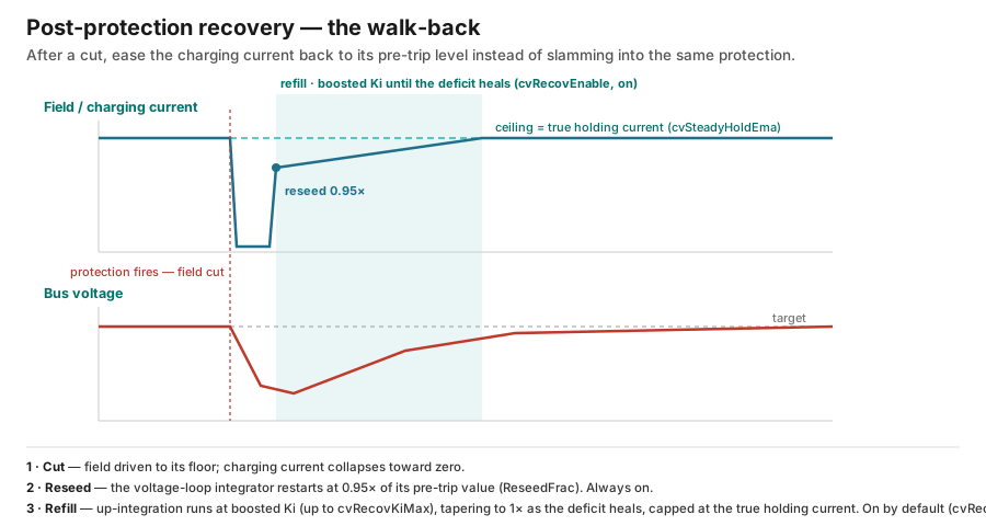
The always-on part — the reseed. When every protection clears, the voltage-loop integrator is set back to a fraction of its pre-trip value (ReseedFrac, 0.95) — a deliberately modest restart so the field does not leap straight back to full drive. This happens on every release regardless of the setting below.
The switchable part — the integrator refill (cvRecovEnable, on by default). While enabled, on release the voltage-loop integrator's up-integration runs at a boosted rate — VoltageKi_active times a multiplier that starts at cvRecovKiMax (default 5×) and tapers linearly to 1× as the reseed deficit heals — walking the current back up to a ceiling:
- The ceiling is the current that was actually holding the target before the trip. It is taken from a slow average of the loop's command measured during clean operation near the target (
cvSteadyHoldEma), not sampled at the instant of the cut — a real overvoltage event flickers on and off, and each brief gap would otherwise sample a half-drained value and cap the field far below what it needs, sagging the bus. The window can never command more than this ceiling, because asking for more can only overshoot back into the protection that just fired. Over the last stretch of the climb the ceiling is pulled lower still — the arrival flare: insidecvRecovFlareBandV(0.35 V per 12 V of bank) of the target it tapers from the full holding current down tocvRecovFlareFrac(0.85) of it at the target, so the loop arrives carrying almost no surplus rather than the whole pre-trip current. Arriving with the full value is what re-fired the protection on a battery whose surface charge has not yet relaxed; whatever the load genuinely needs, the integrator re-adds afterwards at its own pace. - No separate error cap. Because the refill rides the loop's normal integration path, the existing gates pace it — the anti-windup saturation freeze, the integrator cap, the D-term freeze, and the battery-current ceiling all apply — so the comeback stays bounded without a dedicated voltage-error muzzle.
- The exits: the refill ends when the deficit is healed and the integrator has climbed back to the ceiling; or when the pre-trip current no longer holds the target — voltage stuck low and not rising with the full ceiling already commanded — which releases the ceiling rather than starving the field; or immediately if a new protection fires or voltage control exits.
Turning it off is the honest test of the loop itself: with it off, recovery is the bare loop plus the reseed and the normal anti-windup bleed, so the gains must be tuned to survive a step on their own. Leaving it on can mask a charging-loop gain problem, which is why the switch exists.
Field-decay early release. Separately, once a cut has been held long enough for the field coil to actually bleed out its stored energy (the measured field-decay time, fieldDecayTauMs), the hold is released early rather than waiting out the slower filtered signals. This can only shorten a cut, never lengthen it, and it never releases a load-dump-owned or predictive-trim cut.
Overvoltage cascade — illustrative 12 V defaults
With factory defaults on a 12 V system, in order of escalation:
| Condition | Protection | Action |
|---|---|---|
| Filtered voltage ~0.1 V over target | Group 2 | Trim current cap |
| Predicted voltage ~0.15 V over target (if enabled) | Group 1 | Trim current cap |
| Alternator current excess near target | Group 3 (iExcess) | Reset integrators, trim cap |
| Alternator current excess below target | Bulk iExcess | Reset integrators, trim cap |
| Battery-current slope spike (load removed) | Load dump | Collapse setpoint and cap to zero |
| Chip-averaged voltage over the hardware limit (lithium: Bulk + 0.3 V) | INA228 hardware alert | Physical field cut |
| Voltage over the absolute trip (lithium Bulk + 0.5 V, flooded/AGM 16 V) | Software hard cut | Immediate field cut, all modes, + adaptive lockout |
| Voltage more than 0.5 V over the trip | Slew-bypass accelerator | Un-slewed field collapse |
| Both sensors outside plausible range | Implausibility | Critical ramp + lockout |
Note the reference difference: the trim margins are relative to the active charging target (bulk, absorption, or float), while the hard-cut thresholds are absolute. For lithium the hardware alert sits below the software cut because it works on a ~1 s average and must catch sustained excursions; the software cut, on the raw per-tick value, wins on fast spikes.
Voltage sensor failure protections
These do not detect a battery problem — they detect that the voltage sensors themselves disagree or read impossible values. All three are active in automatic mode only (they sit below the manual branch).
- Disagreement warning — the two sensors differ by more than
VoltageDisagreeThreshold(0.15 V on a 12 V bank) continuously forVoltageDisagreeTimeout(10 s). Warning ramp + 30 s lockout. - Disagreement critical — a much larger difference (1 V on a 12 V bank, 2 V at 24 V, 4 V at 48 V) sustained for a short debounce (3 s), or either sensor returning not-a-number or near zero (those fire with no debounce). Critical ramp + lockout. See
isVoltageDisagreementCritical(). - Implausibility — both sensors outside the plausible range for the system class (4.5–15.5 V at 12 V; 9–32.5 V at 24 V; 18–60.5 V at 48 V). One bad sensor alone does not trip this. Critical ramp + lockout, no debounce. See
isVoltageSensorPlausible().
For 10 s after a hardware-OV latch clears, the disagreement checks are suppressed — the two sensors legitimately diverge while the field collapses.
Temperature protections
All temperature protections act on TempToUse — the alternator temperature probe by default, or the thermistor input if selected (TempSource). Setting IgnoreTemperature disables the temperature-limit responses (the derating and the T1–T3 cuts) and the stale-data cut (T5); only the task-health alarm (T4) remains, and because the actual field cut for a hung task comes from T5, a hung task under IgnoreTemperature sounds the buzzer but does not cut the field.
T0 — continuous thermal derating (the thermal PID)
Not a fault response — normal steady-state thermal management, described in full on Charging Control. It subtracts a current penalty (thermalPenaltyAmps) from the ceiling before the limit is ever reached, working from a predicted temperature (present value plus rate-of-rise times a lookahead horizon of 60 s). The damage limit is TemperatureLimitF (175 °F), but the derating actively holds a few degrees under it — the effective control setpoint runs about 7 °F below the limit (further below during a blind warm-up before the slope estimate is trustworthy) so the hard cuts below are rarely reached.
T1 — warning ramp
Temperature exceeds the limit by a small margin (TempWarnExcess, 2 °F): warning ramp. Automatic mode only. It throttles the field down but does not fully cut it.
T2 — sustained warning
The T1 condition held continuously for TempSustainedTimeout (2 minutes): the field is cut. The escalation exists because repeatedly bouncing off the warning ramp means derating has failed. Recovery is the ordinary 30 s cooldown — once temperature falls back below the warning margin the field returns automatically; there is no separate latch requiring a manual re-enable or reboot. Automatic mode only.
T3 — critical immediate cut
Temperature exceeds the limit by a larger margin (TempCritExcess, 10 °F): immediate cut, no ramp. Automatic mode only — it sits at the critical rung, below the manual branch, so taking manual control bypasses it. In manual an overheating alternator is not cut by T3; the protections that stay live in manual are the over-voltage and over-current trips above the manual branch.
T4 — temperature task hang
The temperature probe runs in its own task on the other CPU core (Core 0; the control loop runs on Core 1). A heartbeat monitor (checkTempTaskHealth(), deadline TEMP_TASK_TIMEOUT, 20 s) raises the alarm condition if the task goes silent. This raises the buzzer condition; the actual field cut comes from T5, which fires on the same silence. The flag clears on the next heartbeat.
T5 — temperature data stale
The primary field cut for any temperature-monitoring failure: no validated reading for about twenty seconds, or readings that are not-a-number or wildly out of range (below −50 °F or above 400 °F). Critical ramp + lockout; recovers automatically on the first valid reading after the lockout clears. Covers sensor disconnects, CRC failures, and hung tasks alike. Staleness is deliberately ignored while the engine is stopped (below ~200 RPM, and for 15 s after spin-up), because the temperature task slows its polling when there is nothing to charge.
Cold-charge lockout
Charging a cold battery damages lithium chemistries (lead-acid tolerates it), so the firmware can lock out charging when the battery is too cold.
- Trigger: board temperature (
ambientTemp, the BMP388 sensor used as a battery-temperature proxy) belowMinChargeTempF(default 40 °F). - Action: the field ramps gracefully to zero and locks out, reason
REASON_BATTERY_TOO_COLD, with a buzzer alarm ("Battery too cold to charge"). A 2 °F re-arm hysteresis (ColdChargeHysteresisF) prevents chatter at the threshold. - Fails open: if the temperature reading is stale or not-a-number, charging is allowed — a dead sensor never blocks charging.
- Scope: automatic mode only (it sits below the manual branch).
- Default ON (
coldChargeLockoutEnable = true). A lead-acid-only installation may turn it off. - Caveat — optimistic proxy: the board sensor reads warmer than true ambient, so this proxy can permit charging when the actual battery is somewhat colder than the threshold. It is a coarse guard, not a battery-temperature measurement — set
MinChargeTempFwith margin. - Settings: Setup → Alternator → Protections (
coldChargeLockoutEnable,MinChargeTempF).
Overcurrent protections
Hard overcurrent (electronic fuse)
Measured alternator current above HardOCTripAmps for a short debounce (HardOCDebounceMs, 20 ms): immediate cut. The trip point is auto-derived a fixed 10 A above the user's maximum table current (MaxTableValue) and recomputed whenever that changes. It is evaluated near the top of the priority ladder, above the manual branch, so it is active in all modes including manual. The global test switch cannot disarm it; its Group 0 toggle (HardOCEnable, default on) can, and that is the only thing that does.
Current alarms (buzzer only)
Two thresholds drive the buzzer but never touch the field: alternator current above CurrentAlarmHigh (100 A), and net battery-current magnitude above MaximumAllowedBatteryAmps (125 A, and only when a battery shunt is present). Both via CheckAlarms() when alarms are armed.
Engine speed gate (RPM gate)
There are four distinct RPM-driven cuts:
- The basic gate. Engine speed below
MinRPMForField(125 RPM, withIgnoreRPMoff) cuts the field — there is no reason to excite the field on a stopped or stalling engine. It sits below the manual branch, so it is automatic-mode only (it does not fire in manual). Recovery is not instant: clearing the gate arms a short recovery delay (RPM_RECOVERY_DELAY, 500 ms) before the field is allowed back. After a confirmed stop (see the next bullet) there is an additional restart confirmation — engine speed must hold at or aboveMinRPMForFieldcontinuously forRPM_RESTART_CONFIRM_MS(2 s) before the gate releases, so a lone noise blip cannot re-energize the field. A real start simply passes through the dwell. - Engine-stopped fast cut. When RPM is held at exactly 0 for
RPM_ZERO_CUT_MS(200 ms), the field is cut immediately (pre-gate, forced reasonREASON_RPM_TOO_LOW), overriding any graceful shutdown ramp in progress and firing in every mode, including manual. On a normal key-off the charging-disabled rung outranks the basic RPM gate, so without this the field would slow-ramp for tens of seconds while still energized — coupling field-PWM noise into the RPM sense input and producing phantom RPM spikes. This path fires at full loop rate regardless of sensor freshness. -
Shutdown spin-down cut. When charging is already disabled and RPM is below the minimum for
RPM_BELOWMIN_CUT_MS(75 ms), the cut is finished immediately rather than slow-ramping — the graceful ramp has nothing to soften below the field minimum, and an energized field only fakes tach readings. The short dwell keeps a lone glitched low reading from chopping the field mid-ramp. -
Tach-lie plausibility cut. The tach says the engine is running, the field is being driven hard, and the alternator is making nothing. Above cut-in speed that combination is physically impossible, so the cause is one of three: the speed signal is noise (field-PWM coupling into the sense front end), the alternator is dead, or the field drive is open so the commanded field makes no current — an ON/OFF switch left off, a loose field wire, or a failed field-drive transistor (Q3 / gate drive). The first two waste battery through the field; the open-drive case wastes nothing, but the immediate cut is the right response to all three. Trigger: engine speed at or above
MinRPMForField, the loop commanding more thanTACH_LIE_MAX_AMPS(2 A), applied duty at or above the arm bar, and alternator current magnitude belowTACH_LIE_MAX_AMPS(2 A), all held forTACH_LIE_DWELL_MS(3 s). Both bars are relative to the commissioned install, never a flat duty number: the arm bar is the per-RPM minimum-field floor plusTACH_LIE_HEADROOM_FRAC(15 %) of the remaining span up toMaxDuty, because duty parked at that floor with the loop commanding nothing is the normal, correct zero-output state — the floor is defined as the most field that still makes about no current. The commanded-current bar also covers slew lag, where a rev-up drops the floor faster than duty can follow. It cuts immediately (REASON_TACH_IMPLAUSIBLE) and arms its own escalating lockout — 15 s, 30 s, 60 s, then a 120 s cap, reset after 10 minutes with no trip. Manual mode and an ignored tach (IgnoreRPM) are exempt by design, a stale current sensor cannot fake the zero, and the commissioning sweeps that deliberately hold high duty at zero output below the onset knee (field curve/knee, system ID, field-decay drain, protection-actuation tests) are exempt as well. The detector has its own persistent Enable switch,TachLieEnable(default on) — it ignores the global protections test switch, so this is its only disarm, and turning it off also clears an in-flight lockout.There is deliberately no release on the speed signal dropping away. A phantom is sustained by field PWM, so the cut itself drives the reading to zero — releasing on that would discard the ladder tier on exactly the fault the ladder exists for. The only early exit is a sustained rev-up, and it is doubly guarded: no release decision at all for
TACH_LIE_RELEASE_BLANK_MS(6 s) after the cut, because the field collapse slams the tach front end, then speed must hold above 1.5× the latched trip speed forTACH_LIE_RELEASE_HOLD_MS(300 ms) continuously. Otherwise the tier simply runs out — which for a stopped-then-restarted engine has usually elapsed already.
A grace mask (rpmDropoutGrace) suppresses the gate briefly after protection clamps, after field-cut tests, and after any abrupt protection cut (g_lastFieldCutMs, stamped in applyImmediateCut()), so the sense front-end's post-event dropout cannot be misread as a stall. The abrupt-cut term is a separate stamp because a clamp and a cut are different events — the clamp stamp is never reached on a cut path, and the garbage the tach front end emits afterwards is a non-zero ramp, so neither the clamp term nor a zero test catches it. It is deliberately not applied to the two RPM-derived cuts themselves (masking the gate that just fired would re-energize the field against a real stall), and it only masks while there is something to protect: a commissioning ramp in progress, or charging enabled.
System-level safeties
Hardware watchdog
A task watchdog timer (configured via esp_task_wdt_config_t / esp_task_wdt_reconfigure() in Xregulator.ino, with trigger_panic set) reboots the processor if the main loop stops feeding it for sixteen seconds (WDT_TIMEOUT_MS). Only the main loop task is registered; long blocking work (TLS, file I/O) feeds it inline. On reboot all GPIO pins reset low, which itself cuts the field driver — a hang fails safe. The reboot cause is captured for the reset-forensics record.
The one deliberate exception is an over-the-air update attempt. A single HTTPS call inside it may legally block for the TCP connect, TLS handshake and header wait in sequence with no opportunity to feed, so performOTAUpdateToVersion() widens the panic window to OTA_WDT_WINDOW_MS (5 minutes) for the duration of the attempt and restores the sixteen-second window on every exit path, success or failure (otaSetWdtWindow()). The download loop still feeds inline as well, so a genuinely wedged network stack panic-reboots the (field-off) device within five minutes rather than never.
Alarm buzzer (GPIO21)
Driven by CheckAlarms() (evaluated every 250 ms), aggregating every alarm condition into one steady output on GPIO21. The buzzer is informational only — it has no authority over the field.
Electrical output
The alarm output is a switched 5 V supply driven through a current-limited high-side switch (folds back at roughly a quarter amp, so shorts and oversized loads cannot damage the board) with a built-in flyback clamp diode, so relay coils and magnetic buzzers connect directly. Full circuit details and supported-load table: Warning Buzzer.
Alarm conditions
| Condition | Threshold setting | Default |
|---|---|---|
| High alternator temperature | TempAlarm |
190 °F |
| Low alternator temperature | TempAlarmLow (zero disables) |
32 °F |
| Battery too cold to charge | MinChargeTempF (when cold-charge lockout enabled) |
40 °F |
| High battery voltage | VoltageAlarmHigh |
14.8 V |
| Low battery voltage | VoltageAlarmLow (with a lower disconnect-floor guard) |
11.9 V |
| Low battery state of charge | SocAlarmLow (needs a battery shunt) |
10 % |
| High alternator current | CurrentAlarmHigh |
100 A |
| High battery current | MaximumAllowedBatteryAmps (needs a battery shunt) |
125 A |
| Alternator current pulse-pattern fault | faAlarmEnable |
off |
| Hardware overvoltage latch | any INA228 alert event | — |
| Temperature sensor not responding | staleness window | 20 s |
| Temperature task hung | heartbeat deadline | 20 s |
The temperature-task-hang and hardware-overvoltage conditions are raised regardless of the arm switch (console message and latch), but the physical output stays silent unless alarms are armed (AlarmActivate).
Alarm logic
How the three user toggles, the live condition, and the latch combine:
AlarmTest |
AlarmActivate |
AlarmLatchEnabled |
Condition | Latch | Output |
|---|---|---|---|---|---|
| on | any | any | any | — | ON (auto-clears after the test period) |
| off | off | any | any | any | OFF |
| off | on | off | none | — | OFF |
| off | on | off | tripped | — | ON |
| off | on | on | tripped | set | ON |
| off | on | on | cleared after a trip | still set | ON until latch reset |
| off | on | on | never tripped / latch reset | clear | OFF |
A latched alarm can be silenced by disarming, but returns on re-arm unless the latch is reset (ResetAlarmLatch). New conditions arriving while silenced still set the latch — including the un-gated task-hang and hardware-overvoltage conditions.
Dashboard controls
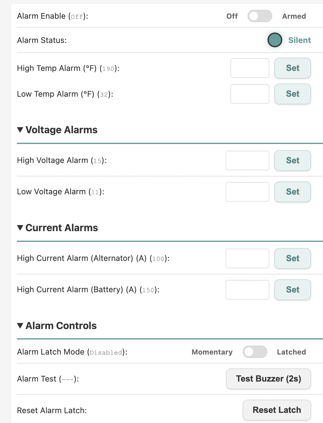
The Alarms panel exposes all of the above:
| Dashboard control | Firmware toggle |
|---|---|
| Alarm Enable (Off / Armed) | AlarmActivate |
| Alarm Status indicator | Alarm_Status |
| Temperature / voltage / current thresholds | the settings in the conditions table |
| Alarm Latch Mode (Momentary / Latched) | AlarmLatchEnabled |
| Test Buzzer | AlarmTest |
| Reset Latch | ResetAlarmLatch |
Mode-by-mode active protections
There are three operating contexts. Manual (ManualFieldToggle) hands the user unrestricted field control, keeping only the protections above the manual rung. Limp Home (LimpHome) is a distinct mode that forces a fixed 30 % duty to get home on failed sensors; handleLimpHome() itself checks only the user Off switch and the hardware-OV latch, but the pre-gate immediate-cut pass runs before it, so the ungated cuts still evaluate — they interact as re-raise oscillation rather than a clean latch, but they are not silently bypassed.
| Protection | AUTO | MANUAL | LIMP HOME |
|---|---|---|---|
| Groups 1 / 2 + current-excess trims | Active (voltage loop engaged) | — | — |
| Load dump | Active | — | — |
| Software hard cut (absolute OV) | Active | Active | Active |
| INA228 hardware alert (physical) | Active | Active | Active |
| INA228 software latch | Active | Active | Active |
| Hard overcurrent | Active | Active | Active (via pre-gate) |
| Sensor disagreement (warning + critical) | Active | — | — |
| Voltage implausible | Active | — | — |
| Cold-charge lockout | Active | — | — |
| T0 thermal derating | Active | — | — |
| T1 / T2 temperature warning | Active | — | — |
| T3 critical temperature cut | Active | — | Active (via pre-gate) |
| T4 temperature task hang (alarm) | Active | Active | Active |
| T5 temperature data stale | Active | — | — |
| RPM basic gate (below minimum) | Active | — | Active (via pre-gate) |
| RPM engine-stopped fast cut (RPM = 0) | Active | Active | Active (via pre-gate) |
| Tach-lie plausibility cut | Active | — | Active (via pre-gate) |
| Current-data stale | Active | — | Active (via pre-gate) |
| Watchdog reboot | Active | Active | Active |
| Buzzer | When armed | Same | Same |
"—" means the priority ladder resolves the mode before that protection is evaluated (manual returns at its rung; automatic-only protections sit below it).
Manual keeps the smallest set — the hardware alert, the software absolute-OV trip, hard overcurrent, the engine-stopped RPM cut, and the watchdog — because the ladder returns at the manual rung and never reaches anything below. Limp Home keeps more: it is not manual mode, so the pre-gate walks the whole ladder, and every reason on the immediate-cut list still fires. What Limp Home drops are the protections that work by ramping (sensor disagreement, cold-charge, temperature warning, temperature-data stale), since it returns before the ramp machinery.
One consequence of "first match wins": a reason that does not cut can mask a lower one that would. Cold-charge lockout sitting true, for example, is returned at its own rung and the critical-temperature cut below it is never reached.