Automatic System Characterization
Once the regulator is wired, its Vessel Info is filled in, and you've set the commonly-adjusted settings for your bank and alternator, run Automatic System Characterization once. It measures how your alternator, engine, and battery bank actually respond, sets the control-loop gains from those measurements, measures the current ripple your alternator produces so the over-current protection can be sized to it, and finishes with a stress test that deliberately fires the over-voltage protection and grades the recovery — instead of leaving you to guess at gains and thresholds.
You launch it from Tuning → Commissioning. The walkthrough is nine steps, most under a minute each; your only job is to hold the engine at the speed each step asks for.
Why it's worth doing
The regulator ships with safe, conservative defaults, but the right control-loop gains and over-current thresholds depend on your specific alternator, belt, and engine. Characterization tunes the gains to your installation so the regulator reacts quickly without overshooting, and measures the ripple you size the over-current threshold against so it sits at the right level. That last point matters even when you hold a fixed voltage target, and especially on large battery banks, where the voltage barely moves as current climbs: voltage-based protection has little to react to, so a correctly-sized over-current threshold is what catches a runaway.
Before you start
- The engine can run and the alternator is producing current.
- The battery has charging headroom — roughly the 20–70% state-of-charge range is ideal. Characterization has to hold a current while it measures, and a full bank won't allow that.
- No other tuning test is running.
- You can hold the throttle steady when asked, and — for the final step — snap it briskly once.
You never touch the field
The regulator drives the field itself throughout. Your only job is to set engine speed when the routine prompts you. Your current settings are saved before anything changes, so you can Abort and revert all at any point and everything reverts to exactly how it was.
Three setup screens before the wizard
The first time through, three short screens come before the wizard itself:
- Prerequisites — confirm the temperature-sensor type and whether a battery shunt (INA228) is installed. Without a shunt, state of charge, the battery-current limit, and float charging are unavailable, so this is worth getting right first.
- Charge Rate Limits — the table that caps how much current the alternator may produce at each engine speed. You fill in two columns: High is your system's full capability, Low a gentler rate (recommended: half of High). Commissioning normally runs in Low; when it finishes, the regulator offers to switch you to High for everyday use.
- Engine Speed Alignment — set the pulley ratio and adjust the scaling factor until the RPM the regulator reports matches your tachometer. Every later step prompts you for engine speeds, so this has to agree with your tach first.
The nine steps
Each step shows its instructions on arrival, runs when you press its button, then shows you what it measured and proposes — nothing is written until you accept. This is the first screen of the walkthrough:
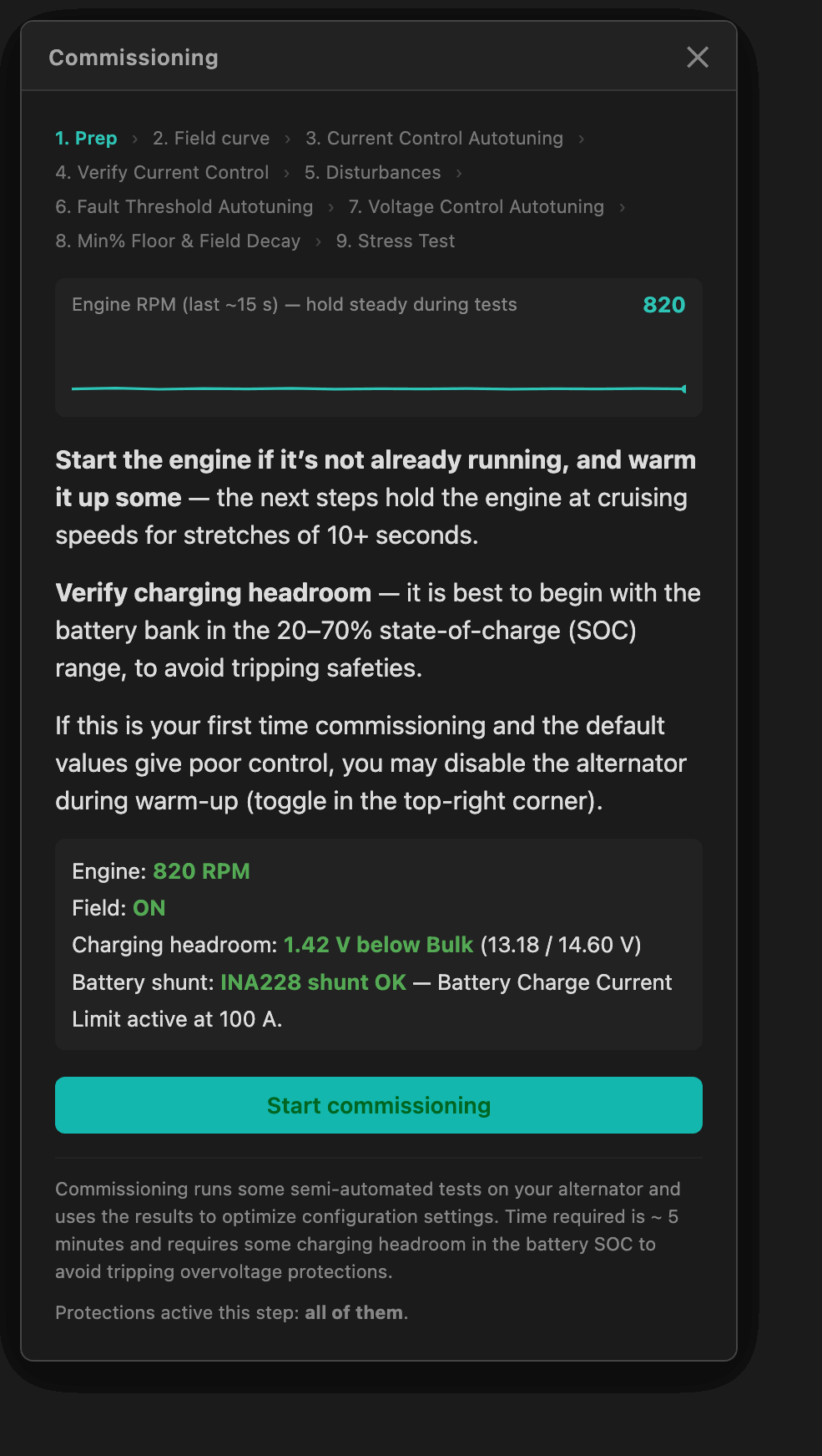
- Prep — checks the preconditions (engine running, charging headroom) and snapshots every setting the wizard might touch, so Abort can restore it all.
- Field curve — sweeps the field drive over its full range with no feedback control (open loop), mapping drive → amps and finding where the alternator stops giving more current (the saturation knee).
- Current Control Autotuning — runs a small open-loop sine sweep to measure the field coil's electrical lag, then proposes the current-loop gains and filter time constants.
- Verify Current Control — drives the newly-tuned loop through a closed-loop sweep from slow to fast, confirming it tracks without ringing and finding the speed it can actually follow (the bandwidth).
- Disturbances — a throttle-driven game maps the current ripple your engine, belt, and alternator actually produce at each engine speed, for the alternator over-current detector.
- Fault Threshold Autotuning — parks the over-current trip lines a safety margin above that measured ripple, and sets the voltage-loop damper's tolerance the same way.
- Voltage Control Autotuning — pulses the charge current and measures how stiff the battery is (how many millivolts it moves per amp) at the voltage loop's own reaction timescale, then proposes the voltage-loop gains.
- Min% Floor & Field Decay — at three held speeds with the engine fully warm, finds the lowest field drive that produces any output (the Min% floor) and times how fast alternator output dies after a protection cut — the number the over-voltage response uses to decide how long to hold the field down.
- Stress Test — deliberately provokes the over-voltage protection with a throttle snap and grades the recovery. The final exam; it has its own page. It writes no settings, so it is optional — skipping it still leaves the device Commissioned.
Protections during the tests
The measurement steps that drive the field directly — Field curve, the two current-loop steps, Voltage Control, and Min% Floor & Field Decay — run with the normal current-based protections paused (they would fight the measurement), but the fast over-voltage hard shutdown stays live the whole time; it is never disabled. Every other step, including the Stress Test, runs under full normal protection. Each wizard screen states which case applies at the bottom.
Pausing, resuming, and re-running steps
Closing the wizard with the X pauses it — each completed step's result is already saved, and the Commissioning tab shows exactly where things stand:
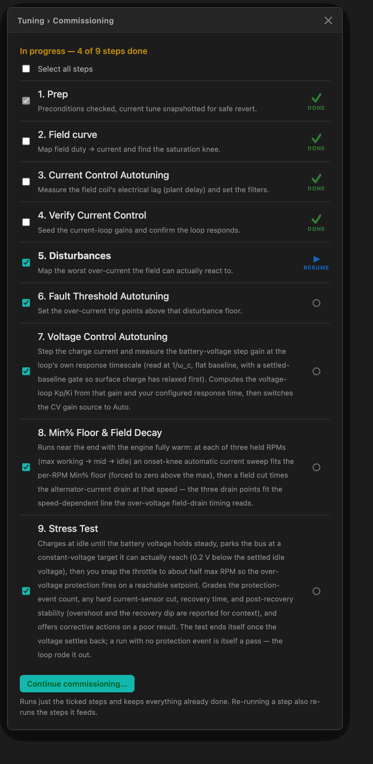
- The checkbox on each row selects it for the next pass, so you can run just the steps you want. Steps feed each other, though: re-running the Field curve re-runs the current-loop and voltage-loop tuning built on it, and re-running Disturbances re-runs Fault Threshold Autotuning. Ticking a step automatically ticks the steps it feeds. The Stress Test is the exception: a re-tune upstream of it clears its tick mark, because the verdict no longer describes the loop you now have — but it is not added back to the plan automatically. It writes nothing and is optional, so re-selecting it is left to you. Min% Floor & Field Decay is independent — nothing feeds it.
- Skip for now sets a step aside but keeps it flagged as outstanding; Mark done manually counts it as complete without a measurement, and the checklist marks it MANUAL so that stays honest.
- Abort and revert all (inside the wizard) restores the pre-commissioning snapshot. Clear and restart commissioning on the tab does the same and starts the walkthrough over from the top.
- A reboot only loses the step that was actually mid-measurement; completed steps keep their DONE marks and the wizard resumes at the first unfinished one.
When it finishes
The device is marked Commissioned once the first eight steps are done. The Stress Test is the one exception: it is a reference check that writes no settings, so skipping it neither blocks the badge nor keeps the "not yet commissioned" reminder alive — it still gets its own tick mark, and it still goes stale if you later re-run a step it depends on. If you ran in the Low charge-rate limits, the regulator then offers to switch you to High so the alternator delivers its full output in normal use. You can re-run any step — or the whole walkthrough — at any time from the Commissioning tab, and the regulator will suggest re-running characterization if you later change Vessel Info settings that affect it.
Watching the over-current detector
During normal running, the iExcess over-current detector (Group 3, on alternator current — one detector pair covering both the voltage-holding phase and the current-limited phase) shows a live chart under Settings → Alternator → Protections. It plots the time-averaged amount the measured current sits above what the regulator is commanding, against the threshold that would trip it. A clean run keeps the current trace well under the threshold line; a real over-current crosses it and draws a marker. Use it to confirm the thresholds you set are sitting comfortably clear of normal operation.
See Safeties & Protections for how all the protection layers work together.
If you skip it
The regulator still runs on its conservative defaults — it's safe to use as-shipped. But the control loop may be slower to settle than it needs to be, and the over-current threshold is a generic value rather than one matched to your alternator. Running characterization once is the recommended setup step after wiring and initial settings.
Cross-references
- Initial Settings — Previous step; fill these in first.
- Stress Test — Detailed page on the final step and how its verdict is graded.
- Operating Modes & Power — Next step; how the regulator behaves once it's running.
- Safeties & Protections — How the over-voltage, over-current, temperature, and other protection layers work.